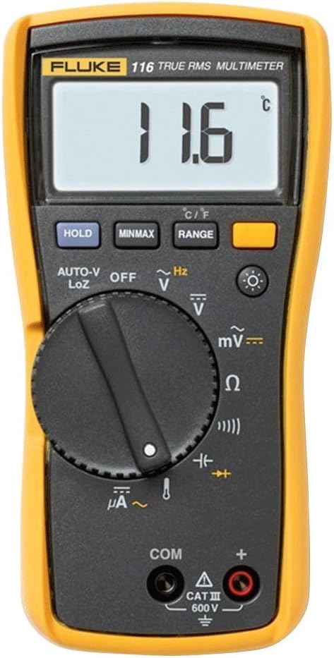
All electronic circuits works on DC and this AC to DC conversion is not possible without bridge rectifiers. Bridge rectifiers are basically ac to dc converters and can be damaged very easily incase of short circuits.
The main aim of this blog is to let you know how to check bridge rectifier with multimeter. You can test a bridge rectifier with both, analog and digital multimeter. For this testing, all you need is best multimeter for electronics work.
Why i am emphasizing in testing rectifiers is because from your home fridges to VFDs almost every equipment has bridge rectifiers. Due to such an abundance of bridge rectifiers you must know how to test the rectifier with a digital multimeter.
What is a bridge rectifier?
A bridge rectifier is used to convert AC voltages to DC voltages. Basically, four or six diodes attached in a bridge form (to convert AC power only), depending upon your input supply. There are basically three types of bridge rectifiers.
- Uncontrolled bridge rectifier
- Semi-controlled bridge rectifier
- Fully controlled bridge rectifiers
Where are bridge rectifiers used?
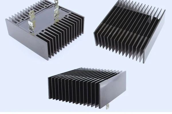
All electronic cards work on DC power supply. These bridge rectifiers are used in making these power supplies. Bridge rectifiers are used in VFDs, inverters and inverter appliances such as fridges, AC and even in automotive. The only drawback of these bridge rectifiers is that they heat too quickly. For this purpose you can use air fans and heatsinks to make them functional. Till now, bridge rectifiers are the most effective way to get DC supply with an efficiency of 80%.
If you want to know how to test power supplies with a multimeter, then you can read my blog about testing power supplies with a digital multimeter.
Factors affecting bridge rectifier performance
There are several factors affecting a bridge rectifier's performance such as other AC inputs voltages, heat, ripple effect, PIV peak inverse voltages.
Input voltage:
The input voltage to a diode bridge is given by a stepdown transformer. If there is a fluctuation in this or other AC input voltage then it doesn't matter if your bridge rectifier is controlled or uncontrolled, it will not provide accurate results. For this purpose, in industries power factor improvers (PFI) are used. Learn how to test Christmas lights with multimeter?
Heat impact:
This heat impact is directly related to the power required at output. The higher the current the higher the power will be, causing a lot of heat. To solve this issue diodes are attached to heat sinks and these heat sinks have been cooled by fans. Learn about Fluke 323 vs 324.
Ripple effect:
In simple words, the ripple effect determines the smoothness of any bridge rectifier output voltages; the appropriate way to improve it is by adding relative capacitors.
Peak Inverse Voltage:
It is basically the capability of diodes. The maximum voltages that a diode produces in the reverse biased circuit are peak inverse voltages. Always check PIV before using any diode for a specific power supply.
Still Confused How to test circuits? Here are more Guides!
How to test bridge rectifier with multimeter?
A typical bridge rectifier is used in many technical applications ranging from voltage regulation in DC power supplies to high current half-wave supplies for tube amplifier circuits. To check the bridge rectifier is very simple, but there are some precautions that must be taken into account when testing a bridge rectifier with a digital multimeter. It is not recommended to only test bridge rectifiers, you should also check capacitors of power supply.
Tools Required
- Multimeter (Fluke 117 True RMS multimeter)
- Test Leads (Fluke TL175E Double Insulated Silicone Test Lead)
- Insulated Gloves (Cut Resistant Gloves)
- Safety Googles (3M Scratch resistant safety Glasses)
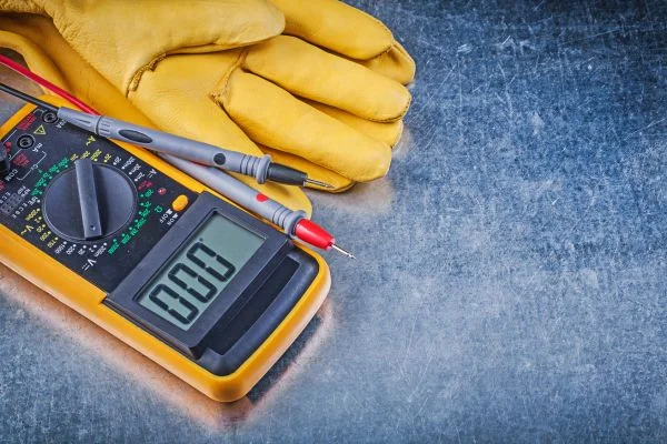
Step by step guide to test bridge rectifier with multimeter
Step 1: Preparation to test a bridge rectifier:
- To avoid possible damage to the device under test and digital multimeter, it is necessary to disconnect the power supply circuit.
- You also have to determine where is the entry and exit of wires, you can recognize which terminals will be used for measurement.
- Multimeter should be set on a small scale (mA or ohm), because if you test a bridge rectifier on a large scale, the digital multimeter will not read the values.
- It is recommended to use insulated terminals probe digital multimeter for better safety.
Step 2: How to measure a bridge rectifier?
- You should set your meter on diode test before taking measurements.
- Measure the positive and negative terminals, which will be marked with emitter base and collector. (Use the multimeter’s positive lead on one terminal).
- If any of the measurements is extremely low or not matching with each other, it could mean that this specific bridge rectifier requires replacement. You can also test it by measuring the negative and positive output of bridge rectifier.
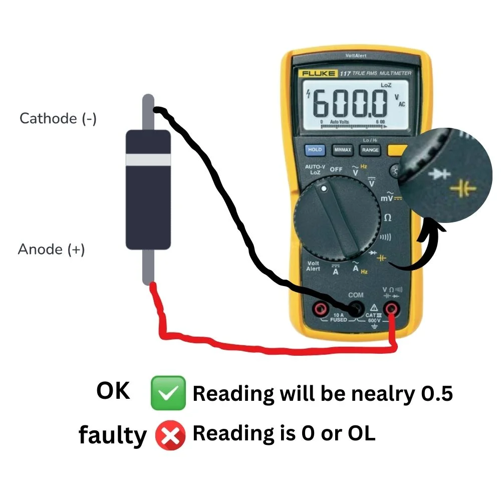
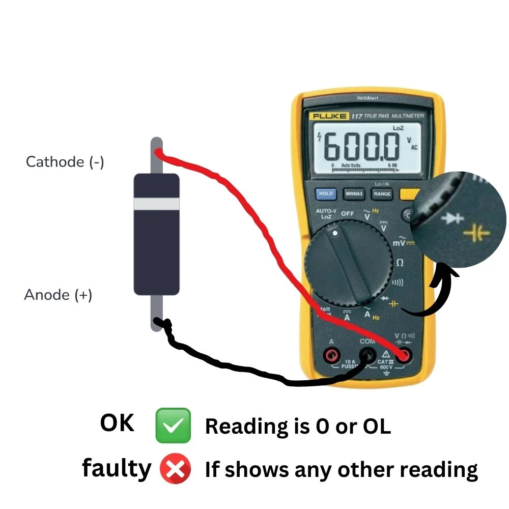
Step 3: How to test a faulty bridge rectifier diode?
- In the same way as testing a bridge rectifier you can test a diode.
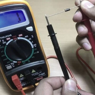
- First, set your meter to measure the resistance in ohms or use the diode tester function.
- Then connect one probe to each of the two terminals of the diode.
- If your meter reads infinite or very high value, it is an open circuit and the diode is in good condition.
- In case of less than an ohm resistance, the diode is shorted and therefore it must be replaced.
- Therefore, at the output of a bridge rectifier there must be a voltage drop (about half of the given voltage).
Troubleshooting of the bridge rectifier
To troubleshoot a bridge rectifier, follow these steps:
- First check for broken wire between the diode terminals and the power source (AC input).
- Check if there are open connections between the diodes (diode conducts electrical signals) and the input power source.
- If you find some broken wire or open connections, resolder them to make sure that they are connected properly.
- You can replace the bridge rectifier with another one that has the same specifications (voltage, amperage).
- Lastly, After replacing a bridge rectifier, you should test it again to be certain that it has functioned properly.
Conclusion
If after testing a bridge rectifier, you find that it has an open diode or a shorted diode, there are several ways to fix it as mentioned above. If you're still with me you might have a clear idea of how to test bridge rectifier with multimeter. Therefore, if you want to know about Variable frequency drives testing then I have also made a separate guide for that.
Also, I would like to ask your help in sharing this article with your friends and family so they get benefits from it. Moreover, most people don't know which multimeter to buy for such electronic works. Being an electrical engineering student, I have made a list of the best multimeters for DIY electronics for this purpose.

