How to test a fusible link? Its not much difficult as it looks. To test a fusible link, follow these steps.
If you want to test an ac relay with multimeter, see my complete blog on it.
"Locate the fusible link, a special wire with a built-in fuse, typically found near the battery or the fuse box. Inspect the link visually for any signs of damage, such as melted insulation or broken wire. Use a multimeter set to continuity mode and connect the probes to each end of the fusible link."
Fusible links are crucial components in electrical systems that protect the circuits from overloads and short circuits.
They are thin wires designed to melt and break the electrical connection in case of excessive current flow, preventing damage to other components or potential fire hazards. Testing fusible links is essential to ensure their proper functioning and the overall safety of the electrical system.
What is a Fusible Link?
It is typically made of a lower melting point alloy than the rest of the wiring in the system.

When excessive current passes through the fusible link, it heats up rapidly and melts, breaking the circuit and preventing further damage to other components. Fusible links are commonly found in automotive electrical systems but are also used in various industrial and commercial applications.
Read more about:8 Best Automotive Multimeters
Importance of Testing Fusible Links
Testing fusible links is crucial because they play a vital role in protecting electrical circuits from damage. A faulty or melted fusible link can disrupt the flow of electricity and potentially lead to electrical fires or damage to expensive components.

Regular testing helps ensure that the fusible links are in good condition and can effectively perform their intended function. By testing these components, you can identify potential issues and take corrective measures before a more significant problem occurs.
Preparing for Testing fusible Links
Before testing a fusible link, you must take essential precautions to protect yourself and the electrical system from harm. Here are some safety measures to consider:

Safety Precautions:
- Ensure that the main power to the circuit is completely turned off before testing the fusible link. This prevents any accidental electrical shock or damage to the testing equipment.
- Use appropriate personal protective equipment (PPE).
- Familiarize yourself with the electrical system and the location of the fusible link to avoid any accidental damage during the testing process.
Read More About: How to test car ECU with multimeter?
Gather the Necessary Tools:
To test a fusible link, you will need the following tools:

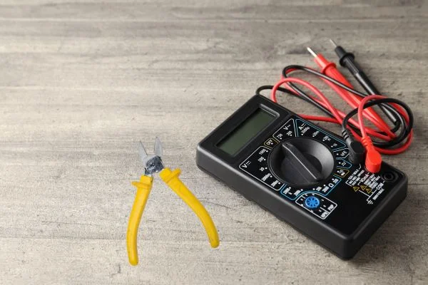
Multimeter: A digital multimeter is essential for measuring continuity and voltage drop across the fusible link.
Wire cutters or pliers: These tools will be required to remove the fusible link from the circuit for testing.
Read more about:7 Best automotive DC clamp meters
Troubleshooting fusible links - Step by Step Guide
How to test a fusible link? Here are the steps involved:

1. Visual Inspection:
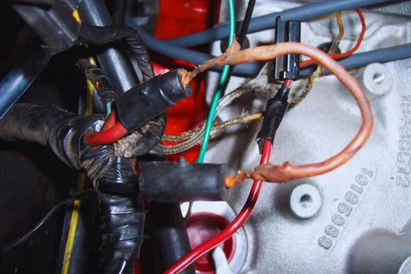
Begin by visually inspecting the fusible link for any signs of damage, such as melted insulation or visible breaks. Additionally, check for loose connections or corrosion, as these can also affect the circuit performance of the fusible link.
2. Removing the Fusible Link:
Carefully disconnect the fusible link from the circuit using wire cutters or pliers. Take note of the exact position and orientation of the fusible link before removing it to ensure proper reinstallation.
3. Testing for Continuity:
Set your multimeter to the continuity testing mode and touch the probes to the terminals or ends of the fusible link. If the multimeter beeps or shows a low resistance reading, the fusible link is intact and has continuity. If there is a low amount of continuity or a high resistance reading, it suggests that the fusible link has blown and needs replacement.
4. Testing for Voltage Drop:

To test for voltage drop, reconnect the fusible link to the circuit. Set your multimeter to the voltage testing mode and touch the probes to both ends of the fusible link while the circuit is active.
5. Resetting or Replacing the Fusible Link:
If the fusible link passes both continuity and voltage drop tests, it can be reinstalled in the circuit. However, if it fails any of the tests, replacing it with a new fusible link of the correct rating is crucial. Avoid using a fusible link with a higher or lower current rating, as it can compromise the safety functionality of the electrical system.
Post-Testing Measures
- After completing the testing process, there are a few additional measures you should take:
Periodicity of Testing:
Regular testing of fusible links is essential to ensure their reliability. In automotive systems, it is often recommended to test fusible links during routine maintenance or when electrical issues or repairs are being performed. Now you know how to test a fusible link.
Structure of A Fusible Link
What's inside a fusible link?
The internal structure of a fusible link typically consists of specific materials carefully chosen to ensure its reliable performance. Let's explore the key components found inside a typical fusible link.

Read More about: how to check car fuses with multimeter?
1. Conductive Wire:
The central element of a fusible link is a conductive wire that carries the electrical current. This wire is typically made of a metal with low resistance, such as copper or silver. The wire's thickness and length are precisely determined to handle normal operating currents without excessive heating. However, when subjected to high currents beyond its rated capacity, the wire generates heat, eventually melting.
2. Insulating Material:
To protect the conductive wire and maintain electrical isolation, a fusible link is surrounded by an insulating material. This material is often a high-temperature polymer or ceramic that can withstand the normal operating conditions of the system. It serves to contain the heat generated during high current events and prevent it from affecting other components or causing damage to the surrounding environment.
3. Enclosure:
A fusible link is enclosed within a housing to provide mechanical strength and protect the internal components. The housing is typically made of a non-conductive material such as plastic or ceramic. It shields the fusible link from external influences, such as moisture, dust, and physical damage, ensuring its reliability and longevity.
4. Activation Element:
The activation element is the part of the fusible link that is specifically designed to respond to high current conditions. It can be a carefully calibrated portion of the conductive wire or an additional material integrated into the link's structure.
The activation element is engineered to have a lower melting point than the other part of the conductive wire. When the current exceeds the fusible link's rating, the activation element is the first to heat up and melt, initiating the break in the circuit.
5. Calibration:
Fusible links are manufactured with specific current ratings to suit different applications. The calibration process involves determining the appropriate thickness and length of the conductive wire to ensure it can carry the normal operating current safely.
Manufacturers also consider the environmental factors and the system's requirements to calibrate the fusible link accurately. Calibration ensures that the fusible link will reliably melt and break the circuit when subjected to excessive current, thus providing effective protection.
6. Mounting and Connection:
Fusible links are designed to be easily installed and connected within electrical systems. They often feature terminals or connectors at each end, allowing for secure attachment to the circuit.
The mounting mechanism may vary depending on the application, ranging from simple clips or bolts to more complex soldering or crimping techniques. The robust connection ensures proper electrical contact and minimizes the risk of accidental disconnection.
How to check the continuity in a fusible link?
To ensure the proper functioning of a fusible link, it is necessary to check its continuity. The instrument commonly used for this purpose is a multimeter.
A multimeter is a versatile testing device that measures various electrical properties such as voltage, current, resistance, and continuity. It consists of several components, including a display screen, a dial or buttons to select the desired measurement mode, and a pair of probes for making electrical connections.
To check the continuity of a fusible link using a multimeter, follow these steps:
1. Set the multimeter to the continuity mode:

Turn on the multimeter and select the continuity mode. Most multimeters represent this mode by a sound wave symbol (∞) or a diode symbol with sound waves.
2. Prepare the fusible link for testing:
Ensure that the power to the main circuit is turned off before proceeding. Locate the fusible link within the circuit. It is typically a small wire or strip of material that is designed to melt when exposed to excessive current. Check the fusible link visually for any signs of damage or melting.
3. Make electrical connections:
Take the multimeter probes and touch the tips to verify that the continuity mode functions correctly. You should hear a beep or a reading close to zero ohms on the multimeter display, indicating a closed circuit.
4. Connect the multimeter probes to the fusible link:
With the circuit still turned off, touch the multimeter probes to the two ends of the fusible link. Ensure that the probes make good contact with the metal or conductor of the fusible link.
5. Check for continuity:
Once the probes are in place, listen for a beep or look for a reading close to zero ohms on the multimeter display. This indicates that the fusible link has continuity, meaning it is intact and allows the flow of electric current. If you do not hear a sound like a beep or the display shows a high resistance value (OL or "open loop"), it suggests that the fusible link has blown and no longer has continuity.
6. Interpret the results:
If the fusible link has continuity, it functions correctly, and the circuit is protected. If the fusible link does not have continuity, it indicates that it has blown and needs to be replaced. A blown fusible link signifies excessive current flowing through the circuit, causing the link to melt and break the circuit.
Conclusion
Notably, fusible links are typically one-time-use devices and cannot be reset or repaired once blown. When a fusible link blows, it is necessary to identify the cause of the overcurrent and address any underlying issues before replacing the link.
Testing fusible links is a critical aspect of maintaining the functionality of electrical systems. By following the appropriate testing procedures and taking necessary safety precautions, you can promptly identify and address any issues with fusible links, ensuring the proper protection of electrical circuits and preventing potential hazards. We hope now you know how to test a fusible link.
FAQs about how to test a fusible link?
How do you fix a fusible link?
To fix a fusible link, you will typically need to replace it entirely. A fusible link is designed to melt or break in the event of an electrical overload or short circuit, protecting the rest of the electrical system. Once a fusible link has melted or broken, it cannot be repaired. You can obtain a replacement fusible link from an auto parts store or dealership that matches the specifications of the original.
How is the continuity test done?
Continuity testing is performed to check for a complete electrical path between two points. A multimeter is typically used in the resistance or continuity mode to conduct the test. The two test leads are connected to the points being tested. If continuity indicates a complete path, the multimeter will emit a beep or display a low resistance value. If there is no continuity, demonstrating an open circuit, the multimeter will not emit a beep or display a high resistance value.
How do I tell if a fusible link is bad?
Inspect a fusible link for physical damage such as melting or discoloration to determine if it is bad. Then, use a multimeter in continuity mode to check for infinite resistance or no continuity. Alternatively, reconnect the link to the circuit, start the vehicle, and measure the voltage drop across the link using a voltmeter. If there is a significant voltage drop, the link is likely damaged.
What testing tool is used to test the continuity of a wire?
A commonly used tool to test the continuity of a wire is a multimeter. A multimeter is an electronic instrument that can measure various electrical properties, including continuity. To test continuity, the multimeter is set to the continuity or resistance mode, and the probes are placed on each end of the wire being tested. If the wire is continuous without breaks or interruptions, the multimeter will indicate a low resistance value or emit a beep sound, confirming the wire's continuity.


